|
A dark field microscope is constructed very similarly to a regular light microscope, but with the addition of a disk before the first lens after the light source. The schematic for the construction of the microscope, with lens focal lengths and distances, is shown below in image 1, and the physical layout in image 2. 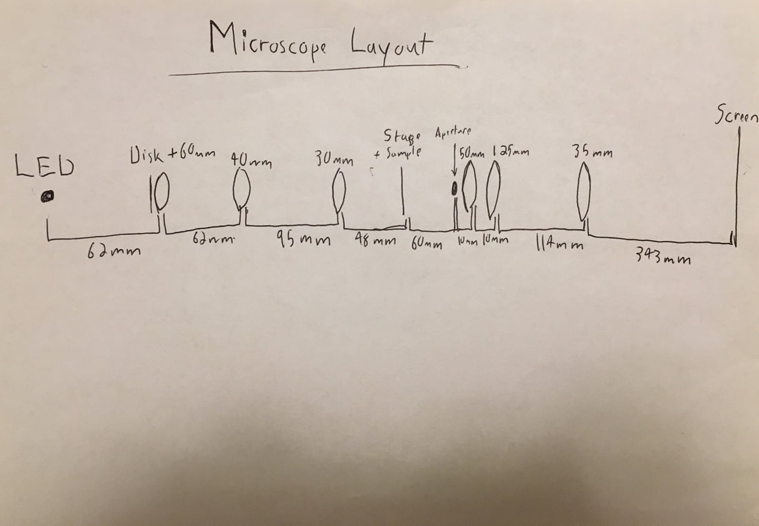 Image 1. Layout of the constructed Microscope 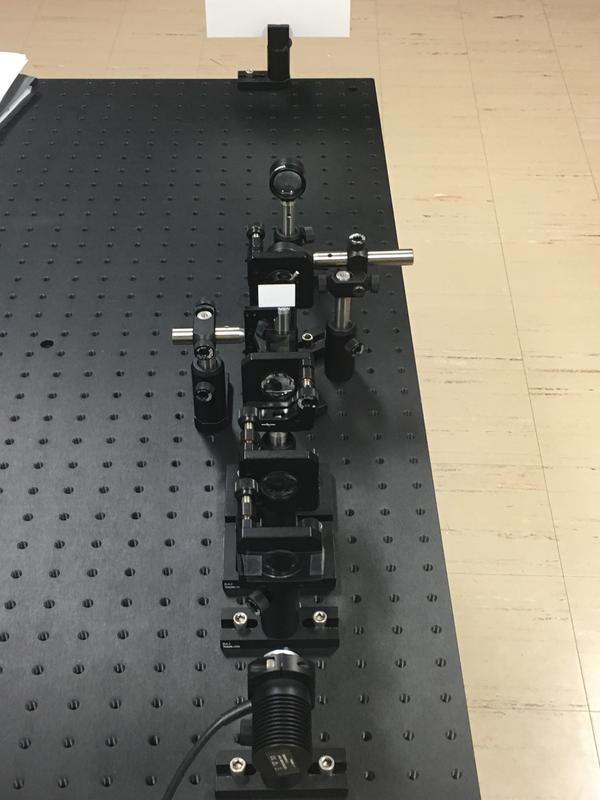 Image 2. The microscope fully set up. The disk causes the light produced by the LED to diffract and then be collected and condensed into a cone by the first 3 lenses. The stage with the sample will then be set at the point where the cone reaches a point. From the aperture on constructs the objective section of the microscope. The difference between a dark field microscope and a regular light/bright field microscope is that only the sample would be illuminated by the light due to the diffraction around the sample. The differences between the 2 are shown below in images 3 and 4. 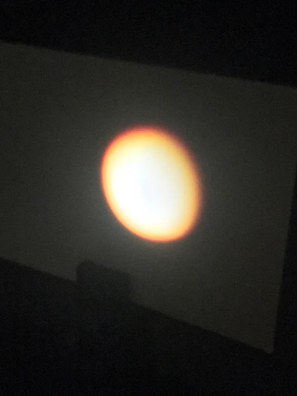 Image 3. Bright field microscope 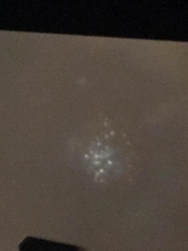 Image 4. Dark field microscope As can be seen in image 4, the gold nanoparticles in the sample show up as bright spots on a completely dark background as opposed to not being visible at all in the bright field microscope in image 3. The resolution was calculated to be 946.9nm through the calculation below. Since it was an LED white light, the wavelength used for the calculation was 550 nm since that lies in the green portion of the visible light spectrum which is the most easily picked up by the human eye. The equation used was r=((0.61)(λ))/((2)(n)(sin(HALF ANGLE))) and is shown in image 5. Image 6 shows the way magnification was calculated, which was done by dividing the height of the image on the end screen by the height of the light on the specimen, which ended up being 17.5 times. 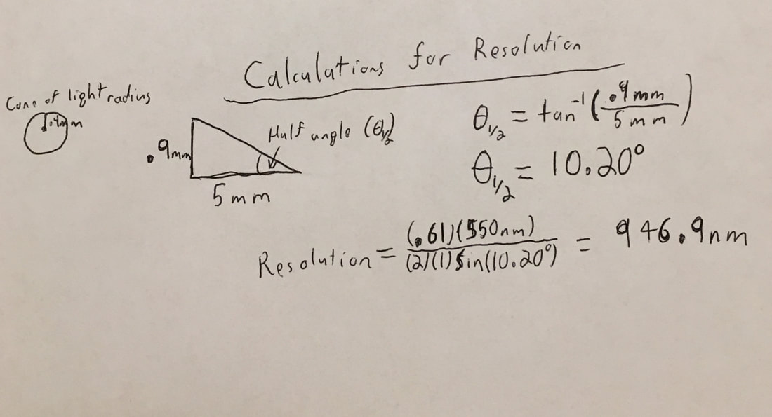 Image 5. Calculation of Resolution 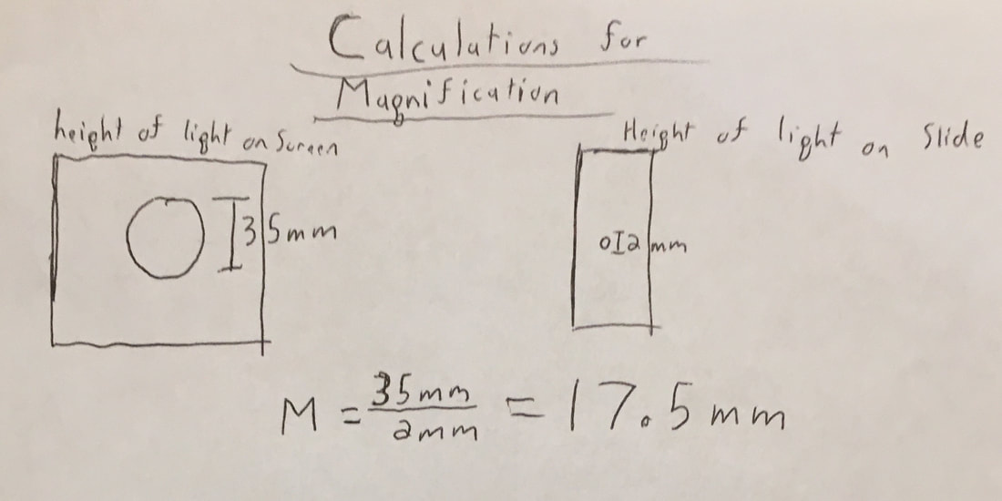 Image 6. Calculation of magnification
0 Comments
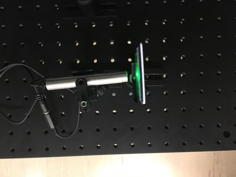
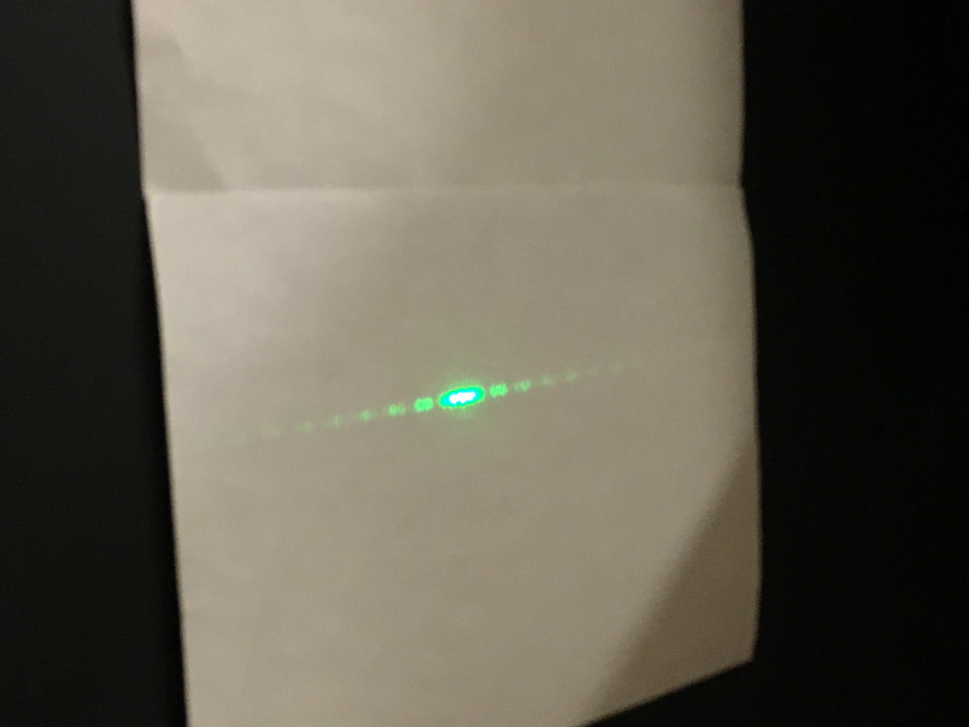
Goal: Construct a telescope out of a series of lenses A Telescope is constructed through a combination of a plano concave lens which would be used as the eyepiece and a concave-convex lens which would be used as the objective lens. The telescope's magnification is determined by dividing the focal length of the objective lens by the focal length of the eyepiece. Upon constructing the telescope, as shown below in Picture A, we had to find out a way to show that it worked correctly. To do so we shined a laser through it and showed that the beam had been magnified upon exiting the objective lens, as shown in Picture B. 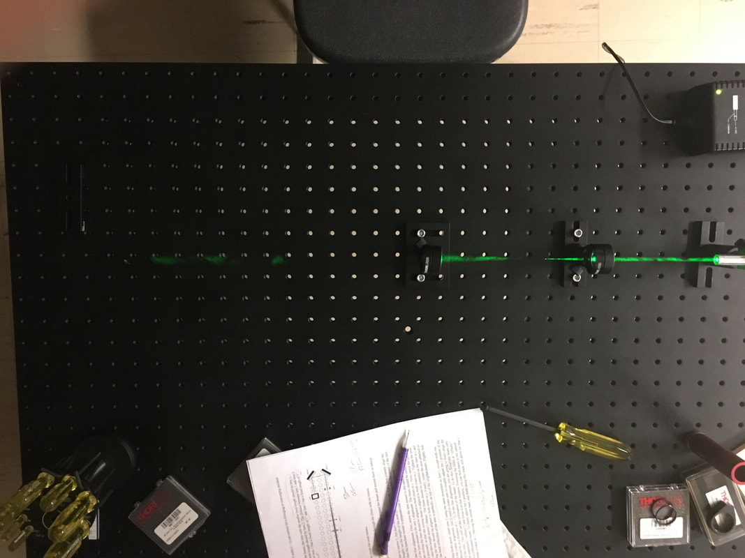 Picture A: Set Up of the Lenses 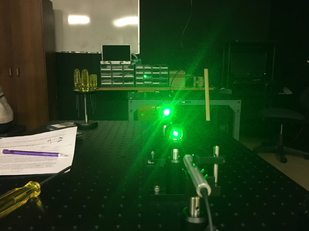 Picture B: Successfully Magnified Goal: To construct a beam expander for a laser out of a series of lenses. First we began by setting up the laser and placing a bi concave lens in front of it and adjusting the laser so that the beam is centered in the lens. We then placed a convex lens at a distance away from the first lens that is equal to the sum of their focal lengths. Once we fully alligned the beam with the two lenses, we tested it to make sure it did indeed expand. As seen in picture A below, we were successful in creating the beam expander 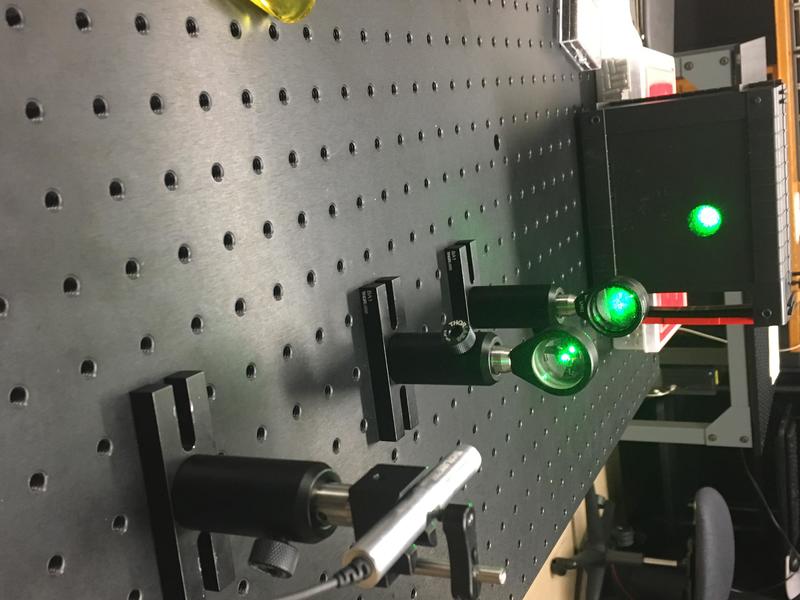 Goal: To use a prism and a laser to find the angle for total internal reflection. First we had to determine what angle to position the laser at in respect to the normal of the prism, which we did through a series of snell's law calculation shown below. The angle needed ended up turning out to be 27.6 degrees. 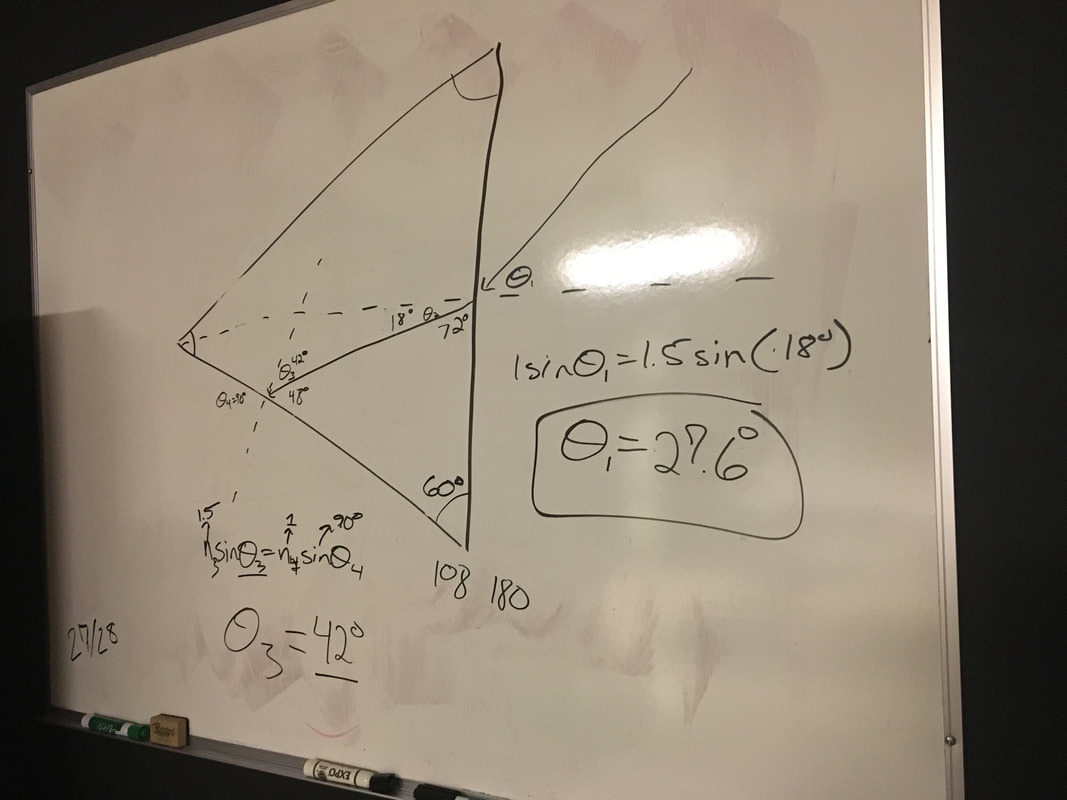 Upon adjusting the laser to the correct angle using a rotating mount, shown below in Image A, we produced the total internal reflection shown in image B below. This occurs because the beam reflects off the internal wall of the prism in a way where none of the light actually leaves the prism at the side due to the difference in index of refraction. 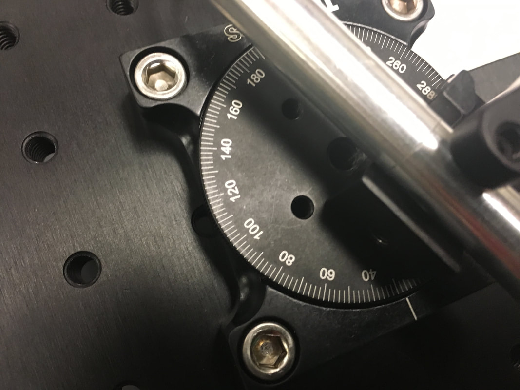 Image A: Rotating mount at 27.6 Degrees 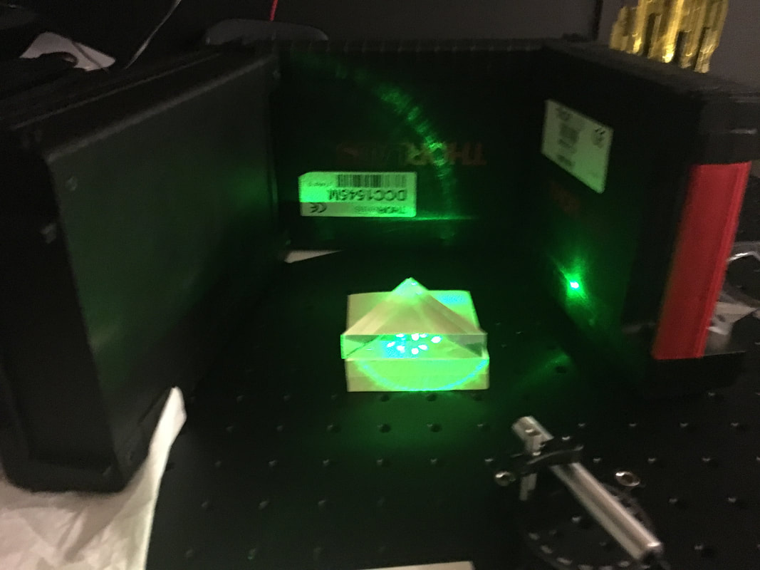 Image B: Note the lack of light leaving the leftmost side of the prism. The goal of this task was to construct a basic microscope out of a series of lenses and apertures. To show that we successfully constructed a microscope we used a small image of a smiley face and magnified it onto a wall, as shown below.  In this section we constructed a Michelson Interferometer to create an interference pattern from a laser. We did so using a laser, a beam splitter, and 2 aluminum mirrors. An overhead view of the layout is shown in the first picture below. 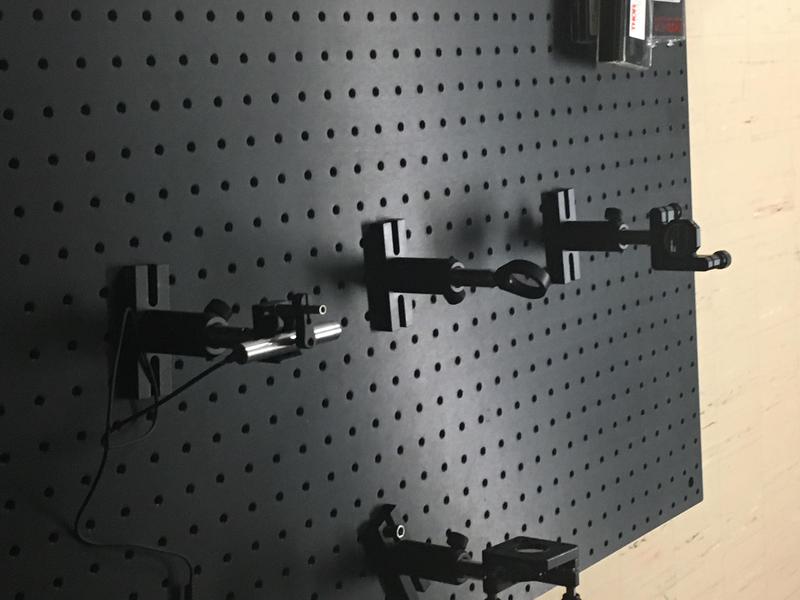 This set up resulted in rings forming around the laser's point when it was in contact with the wall, as shown below. 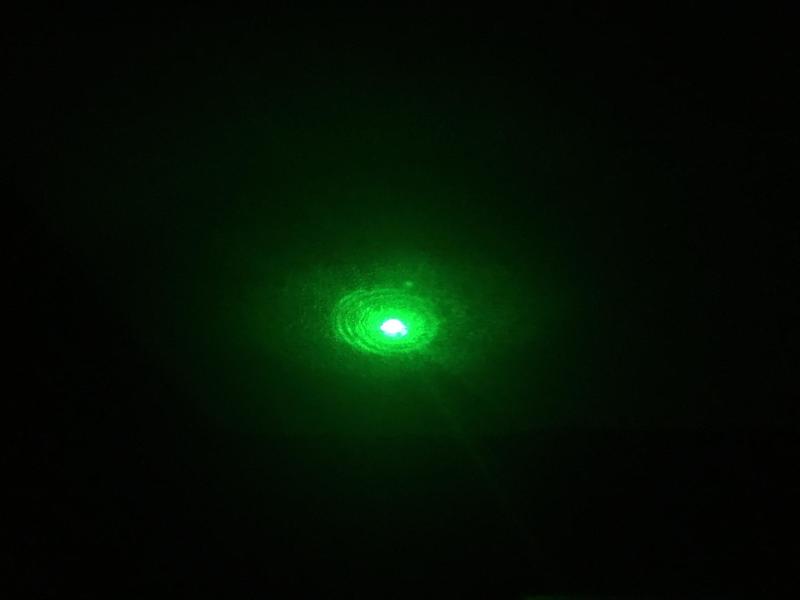 In this section of Task 6, we conducted an experiment based in a Double Slit Interference Pattern. The set up of the laser and slits in the first picture resulted in the interference pattern shown in picture 2.
Poisson’s Spot, also known as Arago’s Spot, is the bright spot located in the center of a dark circular shadow caused by diffraction. This occurs when light from a point source shines on a spherical object and the resulting shadow is projected on a screen perpendicular to the light rays. Due to the wave property of light, the light will bend around the spherical object, and since the center of the shadow is equidistant from everywhere around the edge of the object, the bent light will constructively interfere at the center. Thus, a bright spot will appear in the center of the shadow. This is significant because it displays the wave property of light. This concept is used in dark field microscopy in order to create the cone of light necessary for illuminating the specimen.
Goals: Measure the beam width by using a razor to increasingly block the laser while taking power readings Goal: Build a spatial filter using an optical diagram as the basis |
AuthorChemistry Major at Mercyhurst University ArchivesCategoriesCategories |


 RSS Feed
